Executive Summary & Key Technical Takeaways
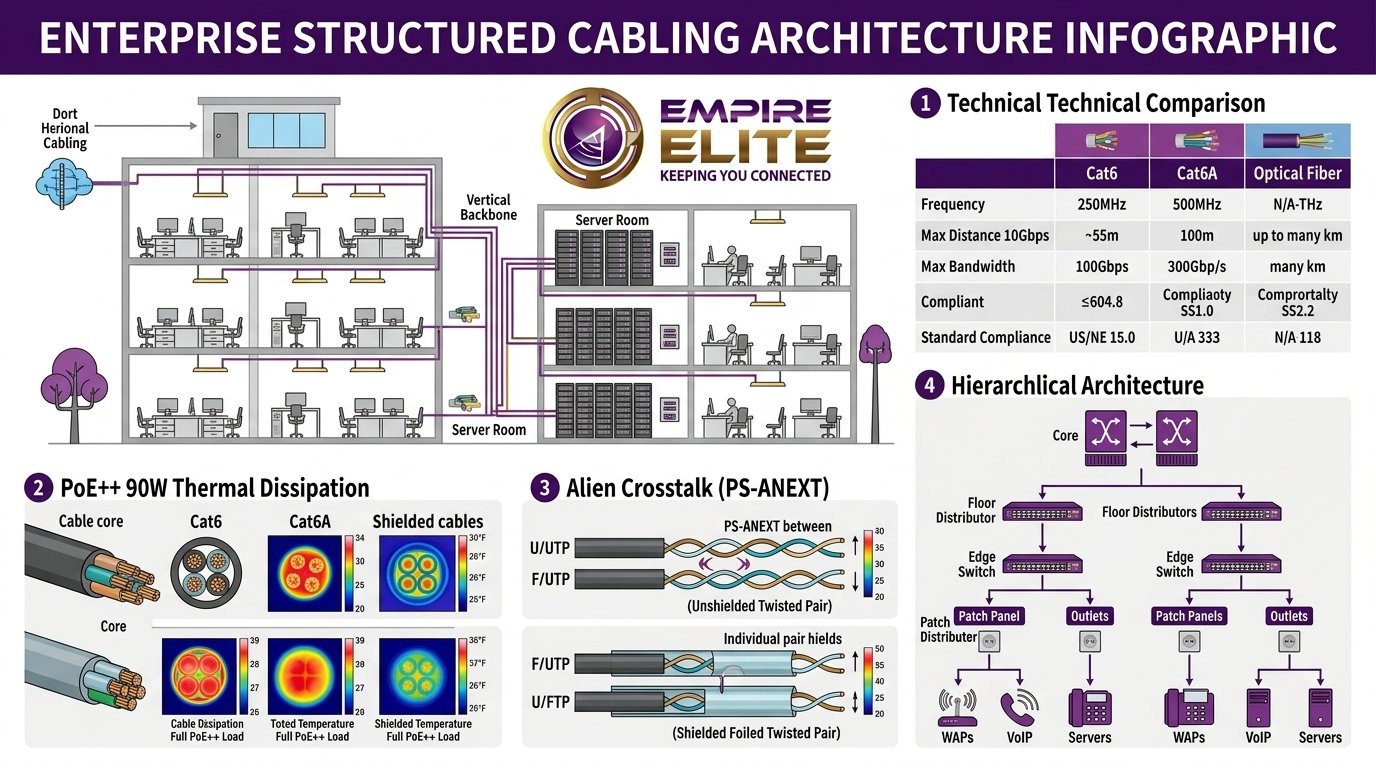
- Cat6 Limitations: While standard Category 6 handles 1 Gbps up to 100 meters, its 10GBASE-T capabilities are physically restricted to 37–55 meters and frequently fail alien crosstalk (PS-ANEXT) tests when bundled in commercial conduits.
- Cat6A Dominance: Category 6 Augmented operates at 500 MHz and guarantees full 10 Gbps transmission across the entire 100-meter channel (90m permanent link + 10m patch cords). It is the required baseline for Wi-Fi 7 access points, 4K IP security cameras, and 10G workstation drops.
- PoE++ 90W Thermal Dissipation: IEEE 802.3bt Type 4 delivers up to 90–100 Watts over four pairs. Thicker 23 AWG Cat6A conductors reduce \(I^2 R\) resistive power dissipation and heat buildup, complying with TIA TSB-184-A bundle limits and preventing cable jacket degradation.
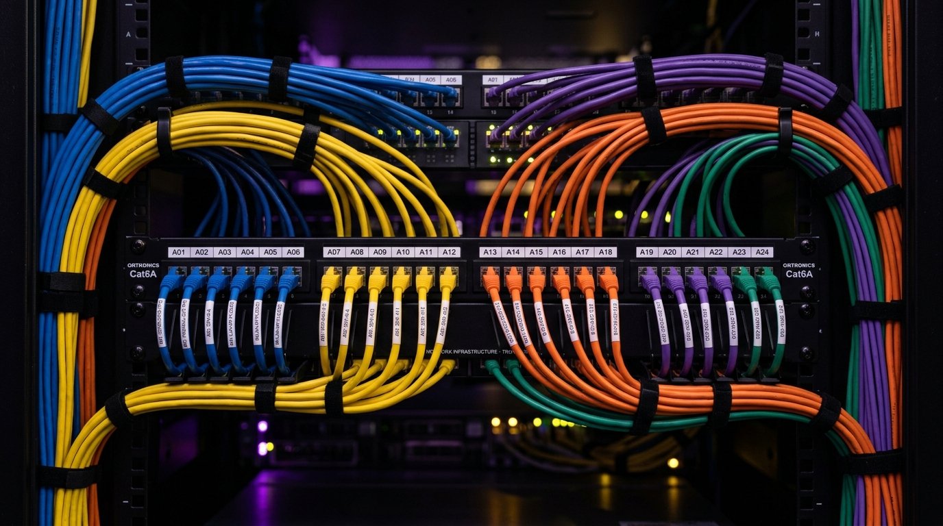
- Pathway & Dressing Physics: Rigid plastic zip ties create local pinch points that distort cable pair geometry, causing severe Return Loss failures. Empire Elite mandates wide hook-and-loop (Velcro) fasteners, 4–5 ft J-hook intervals, and compliance with NEC Article 800 power separation rules.
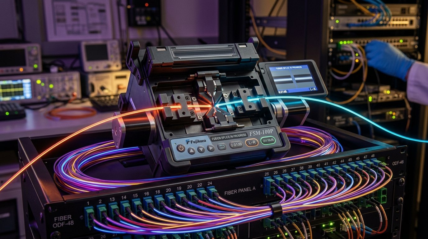
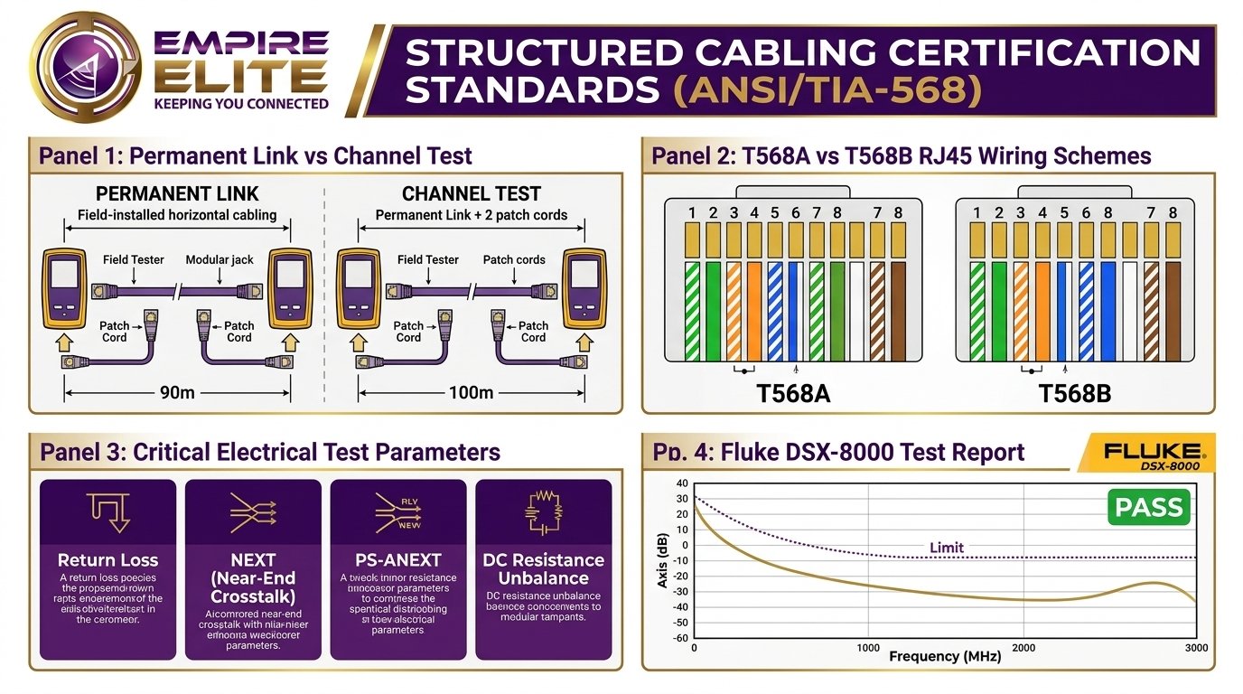
- Fluke DSX Permanent Link Certification: Every cable run must pass rigorous Fluke DSX-8000 certification verifying NEXT, PS-ANEXT, DC Resistance Unbalance, and Return Loss before deployment sign-off.
1. The State of Enterprise Physical Layer Infrastructure in 2026
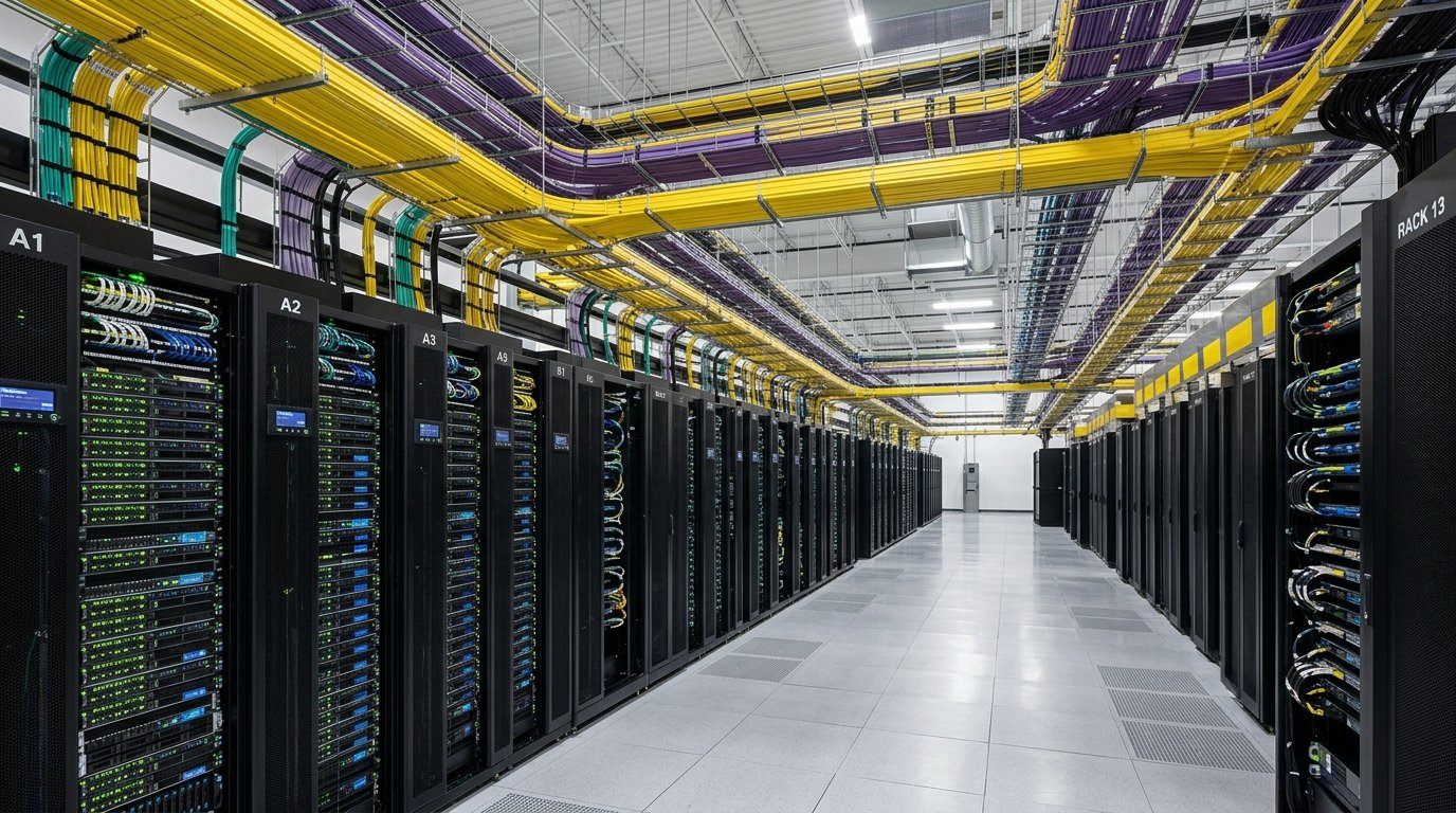
In 2026, enterprise telecommunications networks are undergoing a generational bandwidth transformation. High-throughput Wi-Fi 7 access points (operating on 320 MHz channel widths and requiring dual 10 Gbps PoE++ uplinks), 4K IP surveillance cameras with onboard neural network analytics, multi-gigabit IoT sensor telemetry, and virtualized computing nodes have pushed legacy physical layer cabling past its physical limits.
Over more than two decades of commercial low-voltage design and installation across the Carolinas and regional enterprise facilities, our engineers consistently observe a critical financial reality: the cabling infrastructure represents only 5% to 7% of an enterprise’s overall network hardware budget, yet it causes more than 50% of unexpected network downtime when improperly specified or installed.
Replacing horizontal cabling after commercial walls are sealed, ceilings are finished, and floor tiles are laid can cost 4 to 7 times more than installing the proper media during initial construction. This guide provides enterprise CIOs, facility directors, and lead IT architects with the rigorous engineering data required to make informed physical layer decisions.
2. Cat6 vs. Cat6A: Deep Physical & Electrical Breakdown
Both Category 6 and Category 6 Augmented utilize four unshielded or shielded twisted copper pairs. However, their internal geometry, electrical shielding, and physical dimensions differ substantially under ANSI/TIA-568.2-D and ISO/IEC 11801 Class EA specifications.
| Performance Parameter | Category 6 (ANSI/TIA-568-C.2) | Category 6A (ANSI/TIA-568.2-D) | Optical Fiber (OM4 / OS2) |
|---|---|---|---|
| Specified Operating Frequency | 250 MHz | 500 MHz | Optical Spectrum (Terahertz) |
| 1 Gbps Maximum Reach | 100 meters (328 ft) | 100 meters (328 ft) | 550m (OM4) / 10km+ (OS2) |
| 10 Gbps Maximum Reach | 37–55 meters (Variable / Unrated) | 100 meters guaranteed | 400m (OM4) / 40km (OS2) |
| Conductor Wire Gauge | 23 or 24 AWG solid copper | 22 or 23 AWG solid copper | 9µm or 50µm silica glass |
| PoE++ (90W IEEE 802.3bt) Thermal Rise | High (+15°C to +22°C in 48-cable bundle) | Low (+7°C to +10°C in 48-cable bundle) | Zero heat (Requires Hybrid Copper) |
| Alien Crosstalk (PS-ANEXT) | Uncontrolled at 500 MHz | Strict suppression / internal star spline | Complete optical immunity (0 dB) |
| Cable Outer Diameter (OD) | 5.5 mm – 6.0 mm (0.22 in) | 7.0 mm – 8.5 mm (0.30 in) | 3.0 mm – 6.5 mm (Micro-armored) |
| Minimum Bend Radius (Installed) | 4x Cable OD (~1.0 inch) | 4x to 8x Cable OD (~1.5 – 2.4 inches) | 10x to 20x Cable OD |
Alien Crosstalk (ANEXT) & Geometric Spline Mechanics
In high-frequency data transmission (exceeding 250 MHz), the dominant source of electromagnetic interference is no longer internal pair-to-pair crosstalk within a single jacket. Rather, it is Alien Crosstalk (ANEXT)—the capacitive and inductive electromagnetic energy that leaks between adjacent, parallel cables packed inside trays, raceways, or conduit bundles.
Because alien crosstalk signals originate from neighboring channels, switch digital signal processors (DSPs) cannot cancel the interference through internal cancellation filters. Cat6A eradicates alien crosstalk through three distinct physical innovations:
- Thicker Physical Jacket: An expanded outer diameter physically separates adjacent cable cores, drastically decreasing capacitive coupling according to the inverse-square law of electromagnetism.
- Continuous Internal Polyethylene Star Spline: A central dielectric cross-web separator holds each of the four copper pairs in fixed geometric quadrants, maintaining uniform pair twist rates and pitch along the cable’s entire length.
- Shielding Options (F/UTP vs. U/UTP): In Foiled Unshielded Twisted Pair (F/UTP), a continuous aluminum Mylar foil screen wraps all four pairs, providing complete electromagnetic isolation and zero alien crosstalk.
Budget cabling contractors frequently assert that standard Cat6 can reliably run 10 Gigabit up to 55 meters. In actual field testing with calibrated Fluke DSX CableAnalyzers, whenever Cat6 cables are routed in tight bundles exceeding 12 cables, Alien Near-End Crosstalk (PS-ANEXT) consistently pushes the SNR below operational thresholds. This triggers automatic switch port speed down-negotiation from 10G down to 1G, or causes high packet drops during network peak hours. Never design enterprise 10G links using standard Cat6.
3. Power over Ethernet (PoE++ / 802.3bt Type 4) Thermal Dynamics
Modern structured cabling serves as a unified conduit for both gigabit data and high-voltage DC power. Under the IEEE 802.3bt Type 4 standard, Power Sourcing Equipment (PSE) delivers up to 90 Watts (and up to 100W maximum) of continuous direct current over all four twisted pairs:
- Ipair = Current delivered per pair set (under 90W 802.3bt: 0.960 Amperes across two conductors, or 480 mA per individual conductor).
- Rconductor = Conductor electrical resistance per unit length (Cat6 24 AWG = 8.4 Ω/100m; Cat6A 23 AWG = 6.5 Ω/100m).
- L = Channel length in meters.
Because power dissipation follows the \(I^2 R\) relationship, a 96-cable bundle of Cat6 carrying 90W PoE++ inside an enclosed ceiling conduit can easily experience an internal temperature rise exceeding +25°C above ambient. High temperatures trigger severe degradation:
- Insertion Loss Escalation: High copper temperatures increase electrical resistance. At 60°C, signal attenuation increases by roughly 0.4% per °C for unshielded cables, meaning a 90-meter link designed for 20°C ambient room temperature will fail insertion loss tests in summer heat.
- PVC Jacket Breakdown: Continuous thermal baking causes thermoplastic PVC jackets to become brittle, leading to micro-fractures, short circuits, and off-gassing.
- PoE Spark Arcing Damage: When patch cables carrying 90W are unplugged while active, electrical arcing occurs between the RJ45 jack contacts and plug pins. Empire Elite installs jacks certified under IEC 60512-99-002, ensuring the initial arc occurs far away from the permanent contact seating area.
4. Physical Pathway Engineering & Cable Dressing Physics
A high-performance Category 6A cable can easily fail post-installation certification if field technicians treat it like telephone wire. Category 6A’s high frequencies require strict pathway discipline:
- Hook-and-Loop (Velcro) vs. Plastic Cable Ties: Empire Elite strictly bans plastic zip ties on horizontal communications cabling. When cinched tight with a tension tool, plastic zip ties pinch the four copper pairs together, destroying the 100-ohm characteristic impedance and generating immediate Return Loss failures on testing equipment. We utilize broad, reusable hook-and-loop Velcro fasteners spaced every 12 to 18 inches.
- J-Hook Pathway Spacing: Low-voltage J-hooks and multi-tiered wire saddles must be installed at randomized intervals between 4 to 5 feet apart. Uniform spacing creates resonant cable sag that compounds signal reflection at specific harmonic frequencies. J-hook fill capacity should never exceed 40% to 50% to prevent crushing lower cables.
- Power Line Separation (NEC Article 800 / BICSI): Unshielded data cables routed parallel to high-voltage power conduits (120V/277V/480V) experience electromagnetic induction noise. Maintain a minimum separation of 5 inches from fluorescent lighting fixtures and 12 to 24 inches from high-voltage conduit runs.
5. Where Fiber Optics Must Be Deployed
While Cat6A handles horizontal distribution from the Telecom Room (TR) to workstations and access points, Fiber Optic cabling is mandatory in three primary scenarios:
- Backbone & Riser Runs: Interconnecting the Main Distribution Frame (MDF) to Intermediate Distribution Frames (IDFs) on different floors or across wings.
- Distances Exceeding 90/100 Meters: Any run longer than 328 feet exceeds copper physics and requires optical transmission.
- High-EMI Industrial Environments: Manufacturing floors, proximity to heavy electric motors, elevators, or MRI suites where electromagnetic fields disrupt copper signals.
6. Executive Decision Framework: Choosing the Right Standard
To help CIOs, facilities directors, and general contractors determine the ideal infrastructure, use this direct evaluation checklist:
- Choose Cat6 if: Budget constraints are severe, runs will never exceed 1 Gbps, PoE requirements are limited to basic VoIP phones (15W Type 1), and the facility lease is short-term (< 3 years).
- Choose Cat6A (Recommended) if: You own the facility or hold a long lease, deploy Wi-Fi 6E/7 APs requiring 2.5G/5G/10G uplinks, plan for 90W PoE equipment, or require a guaranteed 15-to-20 year infrastructure lifecycle.
- Choose Optical Fiber Backbone if: You operate a multi-floor campus, data center storage SAN, or require 25G/40G/100G backbone throughput.
7. Certification: Why a Channel Test Matters
An installation is only as dependable as its certification report. At Empire Elite, every terminated drop is tested with calibrated Fluke DSX CableAnalyzers to verify:
- Return Loss and Insertion Loss
- Near-End Crosstalk (NEXT) and Power Sum NEXT
- Alien Near-End Crosstalk (PS-ANEXT)
- Wiremap correctness and DC resistance unbalance
We provide our clients with comprehensive PDF certification binders, ensuring manufacturer 25-year component warranties are valid and audit-ready.
Need an Enterprise Structured Cabling Audit?
Empire Elite delivers turnkey low-voltage cabling, Cat6A 10G certification, and fiber backbone installation throughout Charlotte and the Carolinas with industry-leading manufacturer warranties.
Request an On-Site Cabling Survey