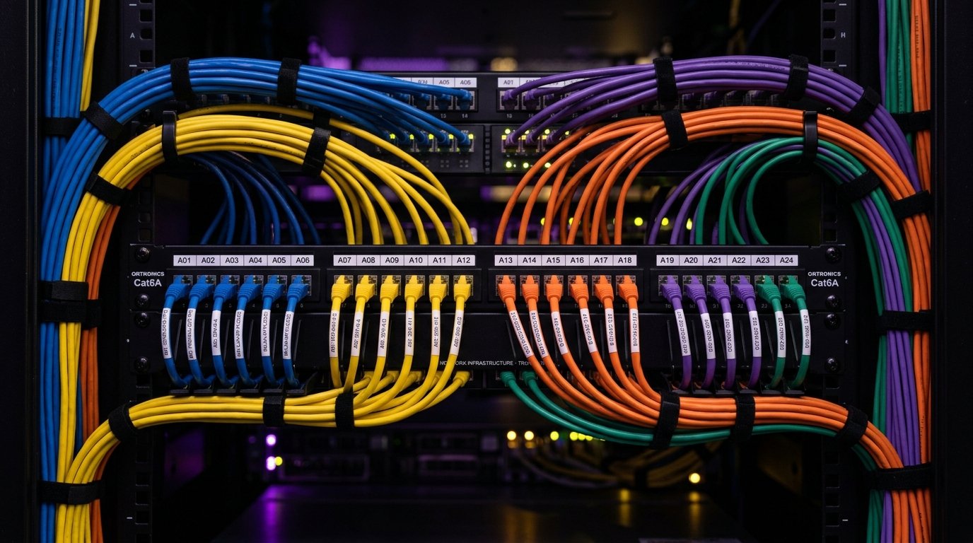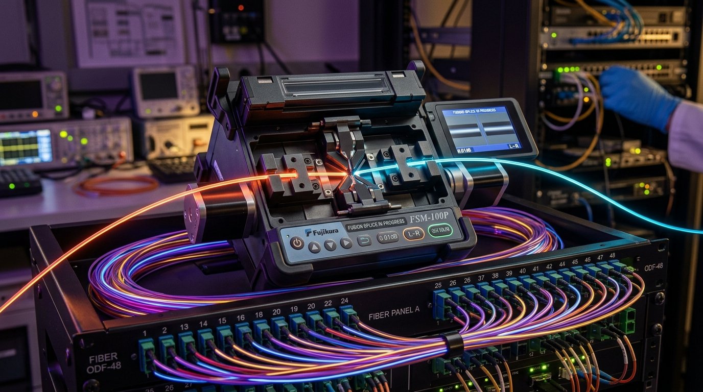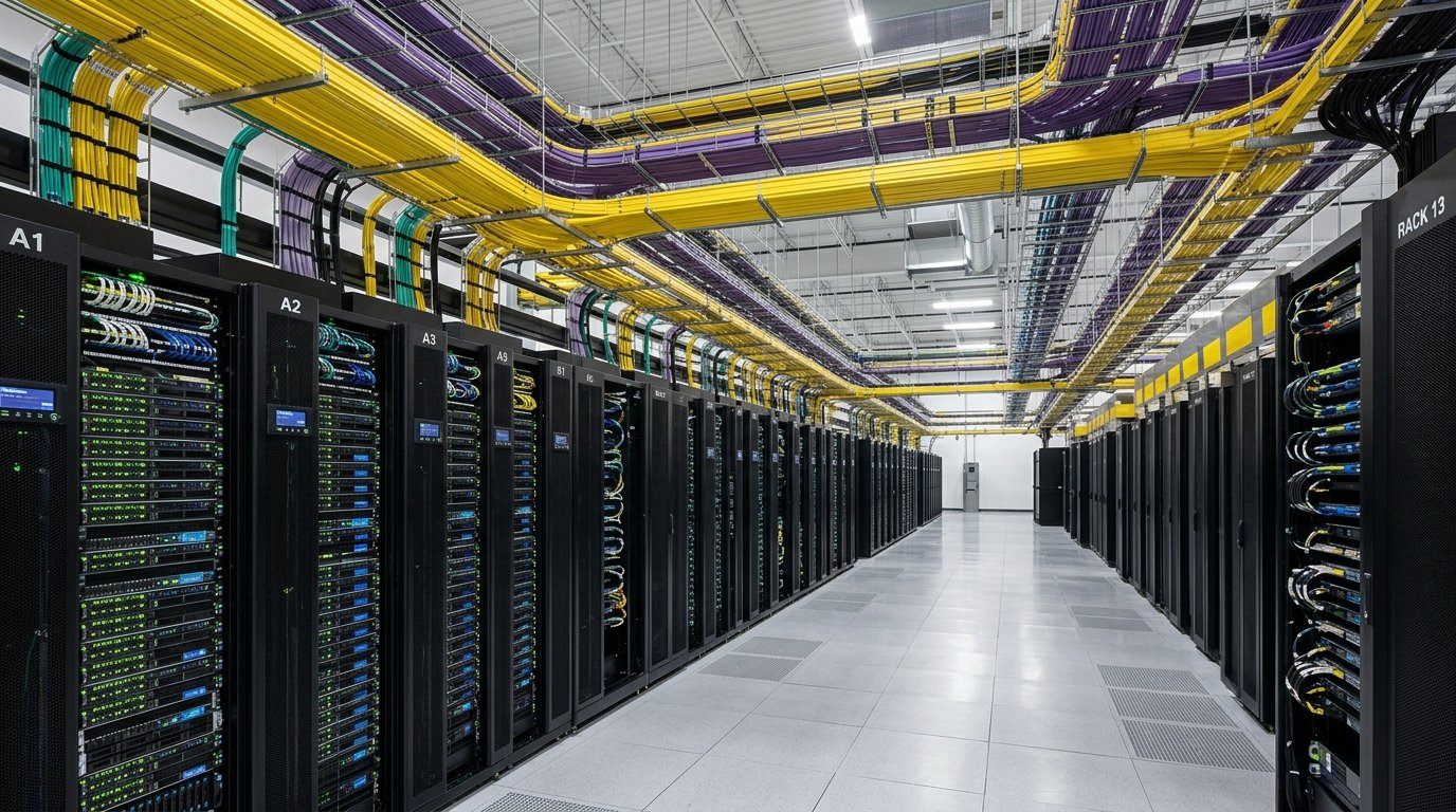
Critical Operational & Engineering Takeaways
- Thermal Obstruction & Static Pressure: Dense "cable spaghetti" draped across rear server exhaust grilles acts as an acoustic and aerodynamic barrier. This generates static backpressure, trapping 45°C+ air inside chassis, forcing fan speeds up to 100%, and triggering thermal CPU throttling.
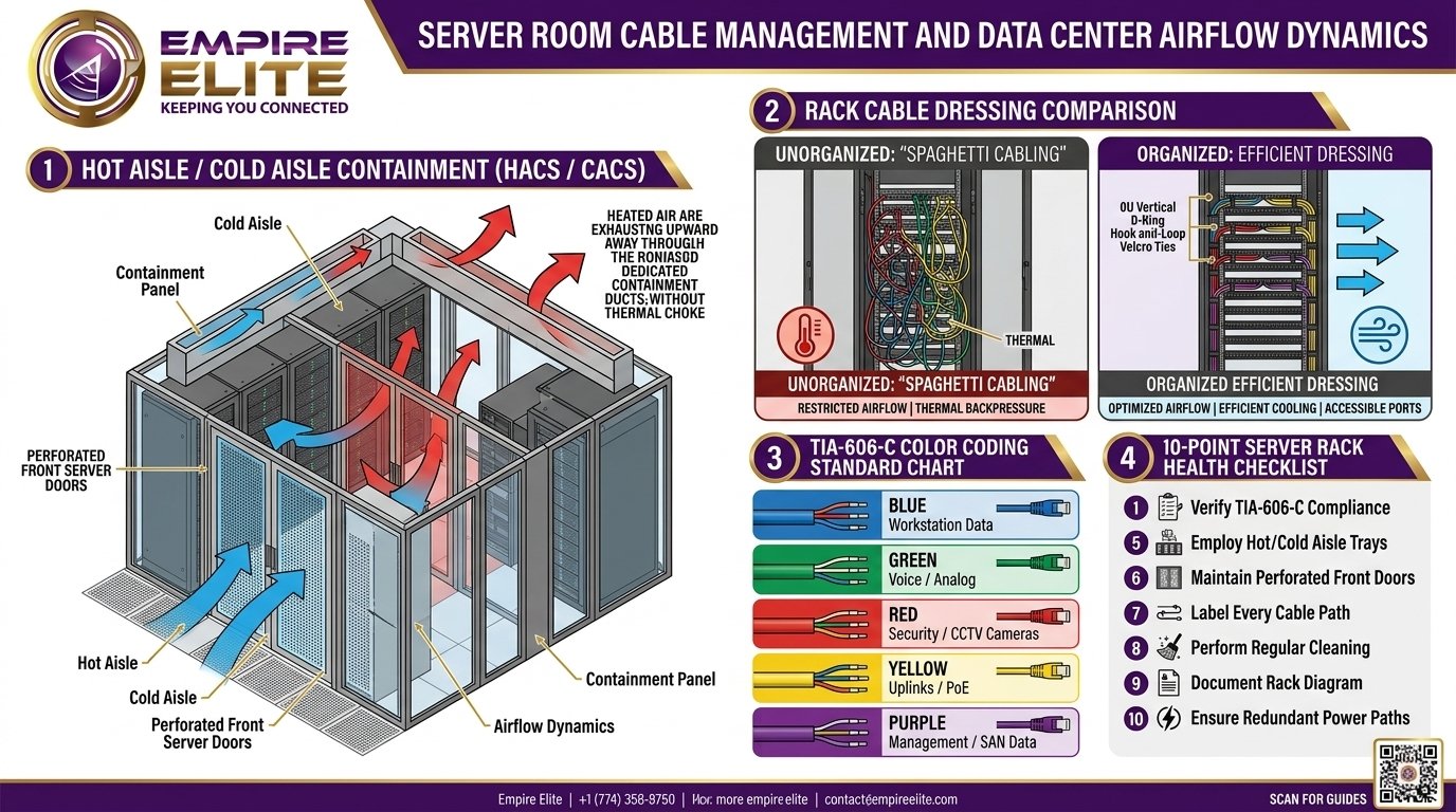
- Hot Aisle / Cold Aisle Containment (HACS / CACS): Implementing strict aisle containment combined with 100% blanking panel utilization prevents bypass air and recirculation, lowering data center cooling energy consumption by 20% to 35%.
- High-Density 0U & 28 AWG Patching: Deploying 28 AWG slim patch cords paired with 0U vertical D-ring organizers reduces bundle volume by 50% compared to legacy 24 AWG cords, clearing direct pathways for front-to-rear server airflow.
- TIA-606-C Standardized Labeling & Color Coding: Color-demarcated cabling (Blue for Data, Green for Voice, Red for Security/Life Safety, Yellow for OS2, Purple for SAN) slashes Mean Time to Repair (MTTR) by over 60% during emergency cutovers.
- Zero Plastic Zip Ties: Ratchet zip-ties compress cable jackets and deform copper pairs ("cold flow"), spiking Return Loss. Empire Elite mandates wide hook-and-loop (Velcro) ties exclusively across all enterprise racks.
1. The Aerodynamics of Server Thermal Choke & Airflow Recirculation
Modern high-density data centers and enterprise server closets operate under the thermodynamic guidelines established by ASHRAE TC 9.9 (Thermal Guidelines for Data Processing Environments). Enterprise servers rely on front-to-back forced-air convection: high-RPM internal fans pull cool conditioned air (recommended intake: 18°C to 27°C / 64.4°F to 80.6°F) through the front perforated bezel, across heatsinks, power supplies, and VRMs, discharging hot air (typically 40°C to 55°C) out the rear perforated doors.
When patch cables, fiber jumpers, and bulky power cords are allowed to accumulate across rear rack posts, they create a dense physical obstruction. In fluid dynamics, this obstruction introduces significant aerodynamic drag and static backpressure:
- ΔP = Static backpressure drop across the rear rack face in Pascals (Pa).
- ξ = Hydraulic resistance coefficient of the cable obstruction mesh (increases exponentially as cable packing density rises).
- ρ = Air density (approx. 1.2 kg/m³ at sea level and standard temperature).
- v = Air velocity exiting the server chassis exhaust fans (m/s).
When rear airflow resistance \(\Delta P\) exceeds the maximum static pressure capability of internal server fans, air volume stalls. This triggers three severe operational penalties:
- Thermal CPU / GPU Throttling: As junction temperatures exceed 85°C to 95°C, onboard server processors automatically reduce clock frequencies to prevent silicone thermal runaway, degrading database transaction speeds and virtualization performance.
- Thermal Recirculation Loops: Blocked exhaust air cannot escape into the hot aisle. Instead, it seeks the path of least resistance, flowing upward over rack tops or recirculating through unsealed 1U open slots back into front cold intakes.
- Accelerated Fan Bearing Wear & Power Waste: Server firmware spins fans at 10,000 to 18,000 RPM continuous duty cycles. A single obstructed 42U rack can waste up to 1,200 Watts of parasitic fan power, generating deafening acoustic noise (> 85 dBA) and accelerating mechanical bearing failure within 12 to 18 months.
2. High-Density Rack Architecture: 0U vs. 1U/2U Cable Management
Achieving optimal server room airflow requires rigorous physical segregation of data pathways, power conduits, and thermal exhaust streams:
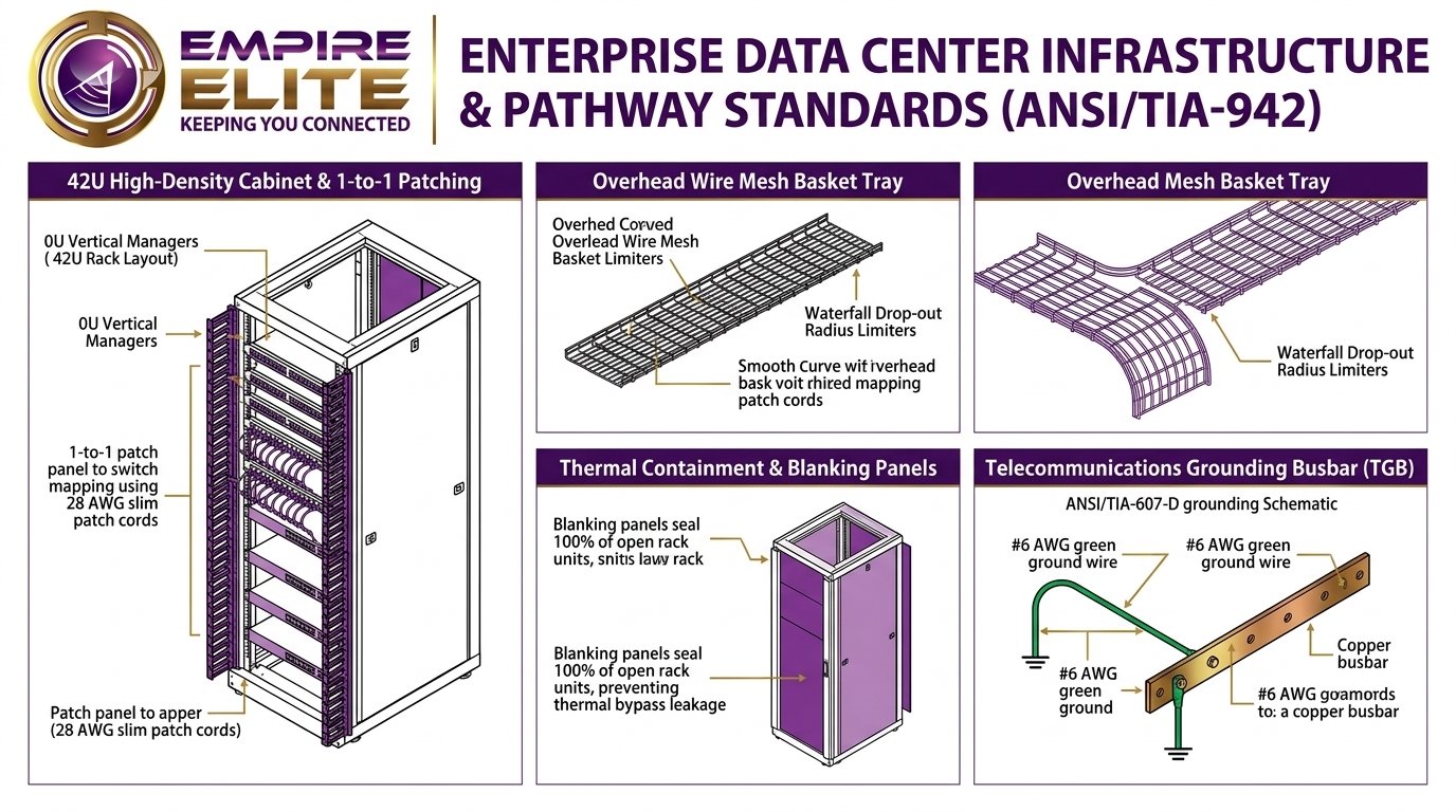
- 0U Vertical Cable Management: High-density cabinets (minimum 800mm wide by 1200mm deep) incorporate dedicated 0U vertical channels situated along the front and rear corners, outside the standard 19-inch equipment mounting zone. Wide-radius plastic fingers guide patch cables directly to their designated rack unit (RU), completely freeing up the central rear chassis area for unobstructed exhaust.
- 1-to-1 Patch Panel to Switch Interconnect: Rather than routing massive 48-cable copper bundles from a top-of-rack (ToR) switch down through 42 rack units, modern best practice places a 24-port or 48-port patch panel directly above or below each network switch. Using 6-inch or 12-inch 28 AWG slim patch cords, connections plug directly across adjacent rack units with zero horizontal slack, eradicating cable loops entirely.
- Blanking Panels & Brush Pass-Throughs: An open 1U slot in a server rack allows up to 30% of hot exhaust air to leak directly back into the cold intake. Empire Elite installs tool-less snap-in blanking panels in every vacant rack space, complemented by brush strip pass-through panels for cable egress points to seal the thermal barrier.
3. TIA-606-C Color Coding Demarcation Standards
In high-pressure outage scenarios, network administrators must be able to visually trace and isolate mission-critical circuits in seconds. The ANSI/TIA-606-C standard establishes a universal color-demarcation hierarchy for enterprise telecommunications infrastructure.
Empire Elite implements the following standardized high-contrast color mapping across all patch cords, jacks, and distribution panels:
| Cable Color & Badge | Designated Functional Role | Termination Target | Operational Priority |
|---|---|---|---|
| Blue | Workstation General Data Drops (Cat6 / Cat6A) | Office Outlets to Floor Patch Panels | Standard Enterprise LAN |
| Green | VoIP Telephony, Intercoms & Analog Lines | IP PBX / Voice VLAN Gateways | Voice QoS Priority |
| Red | IP CCTV Cameras, Access Control & Life Safety | PoE NVR Switches & Security Enclosures | Critical / High Security |
| Yellow | Single-Mode Optical Fiber (OS2) & Core Uplinks | Campus Backbones, OSP & Telco Demarcs | Core Backbone Infrastructure |
| Purple | Multi-Mode Fiber (OM4/OM5) & SAN Storage | Fibre Channel / iSCSI Storage Arrays | High-Throughput Storage Fabric |
| Dark Slate / Gray | Out-of-Band Management (OOBM), iLO, iDRAC, PDU | Dedicated Management Switch Fabric | Administrative Isolation |
Handwritten sharpie labels on masking tape are strictly prohibited in enterprise facilities. Under TIA-606-C Class 2 and Class 3 rules, all cables must feature thermal-transfer wrap-around self-laminating vinyl or polyester labels positioned within 12 inches of each termination point. Labels follow the standardized alphanumeric identifier: [Building]-[Floor]-[Closet]-[Rack RU]-[Port Number] (e.g., B1-F2-TR3-R04-P24), allowing immediate cross-referencing in DCIM management databases.
4. Hook-and-Loop (Velcro) vs. Plastic Cable Ties: Electrical Physics
One of the most persistent bad habits in network cabling is using plastic zip ties to secure copper and fiber bundles.
When a plastic tie is tightened, its hard edges apply non-uniform pressure against twisted pairs inside the jacket. Over time, heat cycles cause copper conductors to press against each other—a phenomenon known as cold flow. This changes the characteristic impedance of the pair, creates signal reflection, and causes random bit errors that baffle network engineers:
- Local Impedance Discontinuities: Compressing Cat6A cables alters the 100-ohm characteristic impedance by up to 15%, causing severe Return Loss failures and packet retransmissions on 10GBASE-T ports.
- Microbending Optical Losses: On optical fiber jumpers, a cinched plastic zip tie induces microscopic bends in the glass cladding. This causes light to escape from the core into the cladding, driving insertion loss above optical budget thresholds.
- Accidental Conductor Severing: When removing a plastic zip tie with flush cutters, technicians routinely nick adjacent cable jackets, triggering catastrophic live network outages.
5. Overhead Cable Pathways & Basket Tray Engineering (NEC 392)
In high-density server rooms, horizontal and backbone distribution cables should be suspended overhead via welded steel wire mesh basket trays or aluminum ladder racks:
- Structural Loading & Tray Fill: Under NEC Article 392, cable depth in trays must never exceed 6 inches, and total calculated weight must stay within structural seismic hanger ratings. Divide trays into dedicated tiers: bottom tier for heavy copper bundles, top tier with solid waterfall drop-outs for delicate optical fiber.
- Waterfall Drop-Out Brackets: When cables transition from overhead trays down into individual server racks, they must pass over curved waterfall bend-radius limiters. Sharp tray edges bend cables past their rated minimum radius, inducing permanent copper fatigue and optical attenuation spikes.
- Grounding & Bonding (ANSI/TIA-607-D): All metallic cable trays, racks, and cabinets must be bonded directly to the Telecommunications Grounding Busbar (TGB) using minimum #6 AWG insulated copper conductor to safely dissipate electrostatic charges and electrical surges.
6. Comprehensive 20-Point Server Room Health & Maintenance Audit Checklist
Empire Elite utilizes this battle-tested 20-point checklist when performing enterprise server room audits, remediation overhauls, and preventative maintenance inspections:
1. Airflow & Thermal Management (Points 1–5)
- [1] Hot/Cold Aisle Alignment: Verify all equipment intakes face cold aisles and exhausts face hot aisles without opposing airflow conflicts.
- [2] Blanking Panel Integrity: 100% of unused rack units (RU) sealed with solid or brush blanking panels.
- [3] Exhaust Air Clearance: Minimum 36 inches of clear rear clearance between server exhaust grilles and enclosure doors.
- [4] Intake Air Temperatures: Cold aisle ambient intake temperature verified between 18°C and 27°C per ASHRAE TC 9.9.
- [5] Perforated Door Open Area: Server cabinet doors maintain at least 65% to 80% open perforation ratio.
2. Cabling Infrastructure & Dressing (Points 6–10)
- [6] Zero Plastic Zip Ties: All intra-rack and inter-rack bundles secured exclusively with hook-and-loop (Velcro) straps.
- [7] Bend Radius Compliance: Copper cables maintain \(\ge 4\times\text{ OD}\); fiber jumpers maintain \(\ge 10\times\text{ to } 20\times\text{ OD}\) at all bend points.
- [8] 0U Vertical Channel Routing: Patch cables routed through vertical finger ducts without spanning horizontally across server chassis.
- [9] High-Density Slim Patching: Utilization of 28 AWG slim patch cords for high-density 48-port switch applications.
- [10] Overhead Waterfall Drop-Outs: All cables entering racks from overhead ladder trays pass over radius-limiting waterfall brackets.
3. Labeling & Documentation (Points 11–15)
- [11] Machine-Printed Labels: Self-laminating thermal-transfer labels on both ends of every cable within 12 inches of termination.
- [12] TIA-606-C Color Adherence: Standardized color coding enforced for Data, Voice, Security, Uplinks, and SAN storage.
- [13] Rack Unit Demarcation: Prominent RU numbering visible on all vertical mounting rails.
- [14] Patch Panel Legend Sheets: Typed, laminated port destination schedules mounted inside cabinet door pockets.
- [15] DCIM / As-Built CAD Up-to-Date: Cable run numbers synchronized with enterprise infrastructure management software.
4. Power, Grounding & Safety (Points 16–20)
- [16] Power & Data Separation: Minimum 5-to-12 inch physical separation between AC high-voltage cords and low-voltage data cables.
- [17] Redundant A/B PDU Feeds: Dual-corded enterprise servers connected to electrically isolated A-feed and B-feed rack PDUs.
- [18] ANSI/TIA-607-D Grounding: All racks, ladder racks, and patch panels bonded to the main telecom ground busbar with #6 AWG copper.
- [19] Cable Tray Weight Limits: Overhead cable loading within structural structural ratings with no sagging tray sections.
- [20] Cleanliness & Contamination: Zero cardboard, packing foam, or dust accumulation within the white space envelope.
Need a Server Room Remediation & Cable Cleanup?
Empire Elite transforms tangled, overheating server rooms into immaculate, audit-ready data centers with zero unplanned production downtime. Contact our infrastructure engineering team today.
Schedule a Server Room Audit