Architectural Summary & Key Engineering Takeaways
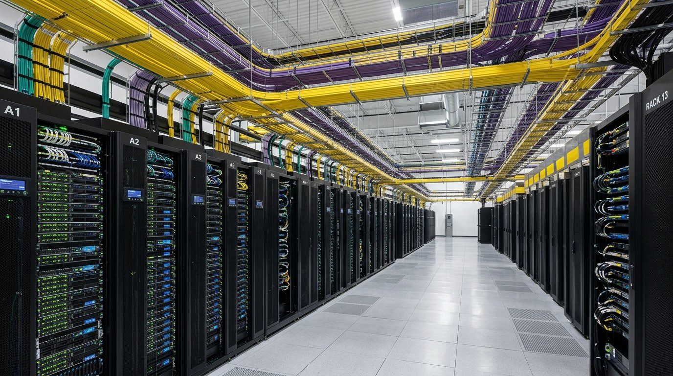
- Core Physics & Modal Dispersion: Multi-Mode (50µm core) allows multiple optical modes to propagate concurrently, creating modal dispersion delay that limits transmission reach to 400m at 10G and 150m at 40G/100G. Single-Mode (9µm core) permits only one fundamental mode, eradicating modal dispersion and unlocking links up to 40km+.
- The Optic vs. Cable Cost Paradox: Bulk OS2 single-mode optical cable is actually 15% to 30% less expensive per foot than multi-mode OM4 cable. However, single-mode transceivers (10GBASE-LR / 100GBASE-LR4) utilize precision DFB/FP laser diodes and tighter alignment tolerances, making them 2x to 4x more costly than 850nm VCSEL multi-mode transceivers (10GBASE-SR).
- Strategic Campus Deployment Blueprint: Deploy OM4 or OM5 inside high-density computer rooms, server rows, and vertical floor risers under 300 meters where port density makes transceiver savings substantial. Deploy OS2 single-mode exclusively for inter-building campus backbones, outside plant (OSP) underground duct runs, and high-speed links exceeding 300m.
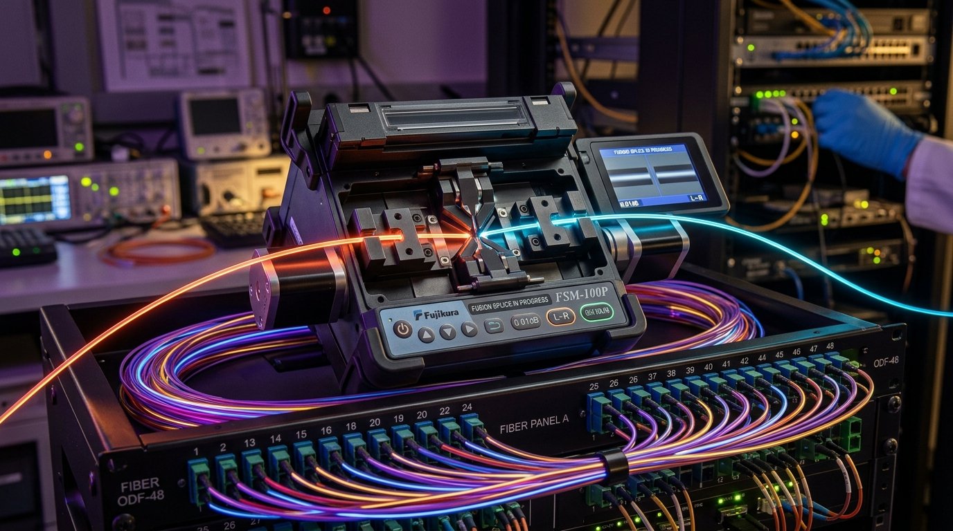
- Termination Integrity: Mechanical field splices degrade rapidly and yield unacceptable return loss (< 40 dB). Core-alignment fusion splicing using automated 3-axis arc alignment is the mandatory enterprise standard, delivering insertion loss ≤ 0.02 dB per splice and return loss > 65 dB.
- Verification & Governance: Every fiber span must undergo bidirectional Tier 1 (OLTS) optical power loss verification and Tier 2 (OTDR) trace event characterization in compliance with TIA-568.3-E and IEC 61300-3-35 end-face contamination standards.
1. Core Physics: Light Wave Propagation & Dispersion Mechanics
In fiber-optic telecommunications, optical waveguides transmit pulses of coherent or incoherent infrared light via total internal reflection. The physical behavior of the transmission medium is governed by Snell’s Law and Fresnel reflection equations at the boundary between the core (refractive index \(n_1\)) and the surrounding cladding (refractive index \(n_2\)), where \(n_1 > n_2\).
The fundamental operational distinction between single-mode and multi-mode systems lies in the dimension of the silica glass core relative to the optical wavelength being transmitted:
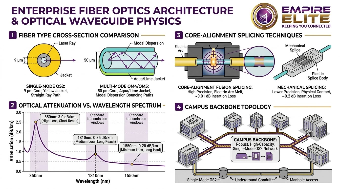
- Multi-Mode Fiber (MMF - 50/125 µm): With a core diameter of 50 microns—approximately five times the wavelength of the light traversing it—the core supports hundreds of distinct spatial transmission paths known as modes. Light entering the fiber at varying incident angles travels different optical path lengths. A light ray traversing along the central longitudinal axis travels a shorter distance than a high-order mode ray reflecting repeatedly against the cladding boundary. This phenomenon produces modal dispersion (intermodal pulse spreading). Over distance, consecutive light pulses spread and merge into one another, creating severe inter-symbol interference (ISI) and bit errors, thereby strictly capping maximum link reach.
- Single-Mode Fiber (SMF - 9/125 µm): In single-mode glass, the core diameter is shrunk to a microscopic 8.2 to 9.2 microns—approaching the exact wavelength of the infrared laser (\(\lambda = 1310\text{ nm}\) or \(1550\text{ nm}\)). Consequently, the core can sustain only one spatial mode: the fundamental transverse mode (\(\text{LP}_{01}\)). Because all light propagates along the same trajectory, modal dispersion is completely eliminated. Single-mode reach is constrained solely by attenuation (optical signal absorption and Rayleigh scattering) and chromatic dispersion (chromatic delay across the optical spectrum).
2. Optical Standards Matrix: OM1 through OM5 vs. OS2
Enterprise network architects must select fiber cabling that satisfies both current transmission rates and two decades of network lifecycle expansion. The following matrix contrasts transmission capabilities across all recognized TIA/EIA-492 and ISO/IEC 11801 optical classifications:
| Fiber Type | Core / Cladding | Light Source | 10G Max Reach | 25G / 40G Reach | 100G / 400G Reach | Attenuation Rate |
|---|---|---|---|---|---|---|
| OM1 (Legacy) | 62.5 / 125 µm | LED (850nm) | 33 meters | Unsupported | Unsupported | 3.5 dB/km @ 850nm |
| OM2 (Legacy) | 50 / 125 µm | LED / VCSEL | 82 meters | Unsupported | Unsupported | 3.0 dB/km @ 850nm |
| OM3 (Laser-Optimized) | 50 / 125 µm | 850nm VCSEL | 300 meters | 100m (40GBASE-SR4) | 70m (100GBASE-SR4) | 3.0 dB/km @ 850nm |
| OM4 (High-Bandwidth) | 50 / 125 µm | 850nm VCSEL | 400 meters | 150m (40GBASE-SR4) | 100m (100GBASE-SR4) | 2.8 dB/km @ 850nm |
| OM5 (Wideband MMF) | 50 / 125 µm | 850–953nm SWDM | 400 meters | 150m (SWDM4) | 150m (100G-SWDM4) | 2.8 dB/km @ 850nm |
| OS2 (Single-Mode) | 9 / 125 µm | 1310 / 1550nm Laser | 10,000m (10 km) | 10km – 40km (LR/ER) | 10km – 40km (LR4/ER4) | 0.35 dB/km @ 1310nm |
Facilities operating orange-jacketed 62.5/125 µm (OM1) cabling installed during the Fast Ethernet or early Gigabit era are facing imminent operational failure. When connecting modern SFP28 (25G) or QSFP28 (100G) optics to OM1 or OM2 glass, high Differential Mode Delay (DMD) and excessive attenuation will trigger continuous optical packet discards, frame checksum errors, and flapping links. Empire Elite routinely performs scheduled hot-cutover migrations to transition legacy riser plants to OM4 and OS2.
3. Transceiver Economics: Cable Cost vs. Optic Capital Expenditure
When planning a campus network overhaul, IT leadership frequently questions why single-mode fiber is not deployed uniformly across all closets, racks, and workstations. The answer is found in the economics of optical transceiver manufacturing.
While OS2 single-mode optical cable is cheaper per linear foot than OM4 multi-mode cable (due to the higher manufacturing volume of single-mode glass worldwide for telecommunications carriers), the transceivers required to illuminate single-mode glass are dramatically more complex:
- Multi-Mode Transceivers (e.g., 10GBASE-SR, 25GBASE-SR): Utilize 850nm Vertical-Cavity Surface-Emitting Lasers (VCSELs). VCSELs emit light vertically from the wafer surface, allowing high-yield batch manufacturing, automated wafer-scale testing, and relaxed mechanical alignment into the wide 50µm fiber aperture. Typical power consumption is low (< 1.0 Watt), and manufacturing costs remain very economical ($18 – $35 per transceiver).
- Single-Mode Transceivers (e.g., 10GBASE-LR, 25GBASE-LR): Require Distributed Feedback (DFB) or Fabry-Perot (FP) semiconductor laser diodes operating at 1310nm or 1550nm. These edge-emitting laser chips require sub-micron precision robotics to align the microscopic laser beam into a 9µm fiber core aperture. Furthermore, single-mode optics incorporate internal temperature-stabilizing thermoelectric cooling (TEC) circuitry to prevent thermal wavelength drift. This complexity increases manufacturing cost ($75 – $250+ per transceiver) and switch electrical power consumption.
The Architectural Rule: In a high-density enterprise data center or multi-story corporate headquarters with 500 server connections, deploying single-mode transceivers at both ends of every 20-meter patch would generate tens of thousands of dollars in unnecessary transceiver overhead. Multi-mode OM4 is ideal for localized high-density interconnects, whereas OS2 single-mode is essential for campus backbones where link distance makes multi-mode mathematically unviable.
4. Calculating Optical Loss Budgets Before Pulling Cable
In enterprise fiber deployments, guesswork is unacceptable. Before any fiber run is pulled through conduit or terminated in an optical patch enclosure, Empire Elite telecom engineers calculate a strict Optical Link Loss Budget. This calculation verifies that total cumulative link attenuation remains safely within the Dynamic Power Range of the transmitting and receiving transceivers.
- L = Total optical cable length in kilometers (km).
- α = Cable attenuation coefficient: 0.35 dB/km for OS2 at 1310nm; 0.22 dB/km for OS2 at 1550nm; 3.0 dB/km for OM4 at 850nm.
- Nsplices = Number of fusion splices in the link (standard budget: 0.05 dB per splice; Empire Elite standard: ≤ 0.02 dB).
- Nconnectors = Number of mated connector pairs in the link path (standard budget: 0.50 dB per mated pair; high-performance LC/APC: ≤ 0.20 dB).
- Safety Margin = Unallocated link margin reserved for temperature fluctuations, laser aging, and future re-terminations: 1.5 to 2.0 dB.
Worked Loss Budget Scenarios: Campus vs. Building Backbone
Scenario A: 2.5-Kilometer Inter-Building Campus OS2 Backbone (10GBASE-LR)
- Link Specifications: 2,500 meters of 24-strand armored OS2 single-mode outdoor fiber at 1310nm, with 4 fusion splices and 2 mated LC patch connector pairs.
- Fiber Attenuation: \(2.5\text{ km} \times 0.35\text{ dB/km} = 0.875\text{ dB}\)
- Fusion Splice Loss: \(4\text{ splices} \times 0.05\text{ dB} = 0.20\text{ dB}\)
- Connector Loss: \(2\text{ connector pairs} \times 0.50\text{ dB} = 1.00\text{ dB}\)
- Safety Margin: \(1.50\text{ dB}\)
- Total Calculated Optical Loss: \(0.875 + 0.20 + 1.00 + 1.50 = \mathbf{3.575\text{ dB}}\)
- Transceiver Validation: A standard 10GBASE-LR SFP+ optic provides a minimum transmit power of \(-8.2\text{ dBm}\) and a receiver sensitivity of \(-14.4\text{ dBm}\), yielding a power budget of \(6.2\text{ dB}\). Because our calculated loss (\(3.575\text{ dB}\)) is well below \(6.2\text{ dB}\), this link operates with an exceptional \(2.625\text{ dB}\) headroom buffer.
Scenario B: 300-Meter Intra-Building Data Center OM4 Backbone (100GBASE-SR4)
- Link Specifications: 300 meters of OM4 tight-buffered riser trunk cable at 850nm with 2 mated MPO-12 cassette connections.
- Fiber Attenuation: \(0.3\text{ km} \times 3.0\text{ dB/km} = 0.90\text{ dB}\)
- MPO Cassette Loss: \(2\text{ mated MPO pairs} \times 0.35\text{ dB} = 0.70\text{ dB}\)
- Safety Margin: \(0.50\text{ dB}\)
- Total Calculated Optical Loss: \(0.90 + 0.70 + 0.50 = \mathbf{2.10\text{ dB}}\)
- IEEE 802.3ba Standard Limit: 100GBASE-SR4 imposes an absolute maximum channel insertion loss of \(1.9\text{ dB}\) at 100m. At 300 meters, signal degradation exceeds IEEE specifications! This demonstrates why 100G speeds across 300 meters require upgrading to OS2 Single-Mode with 100G-PSM4 or CWDM4 optics.
5. Precision Fusion Splicing vs. Mechanical Field Terminations
The integrity of an optical physical layer is overwhelmingly determined at the termination points. Light traversing an uninterrupted 9-micron glass strand encounters virtually zero interference; however, when two strands are joined together, any angular misalignment, physical gap, or surface contamination causes massive signal scattering (attenuation) and reflected light waves (Optical Return Loss).
Comparison of Splicing Technologies:
-
Automated Core-Alignment Fusion Splicing (The Empire Elite Standard): Using precision high-voltage electric-arc fusion splicers (e.g., Fujikura 90S+ or Sumitomo Type-72C+), microscopic CMOS cameras scan the core geometry along the X, Y, and Z axes. The machine independently moves the glass strands with motorized nanometer piezo actuators until core eccentricity is perfectly neutralized. A tailored electrical discharge cleans the cleave faces before a high-power arc melts the silica glass (melting point \(> 1,600^\circ\text{C}\)) into a single continuous optical waveguide.
Performance: Typical insertion loss of 0.01 – 0.02 dB; Optical Return Loss \(> 65\text{ dB}\). Tensile test strength \(> 2.0\text{ N}\). - Cladding-Alignment Fusion Splicing: Common in budget handheld splicers, this method aligns the outer 125µm cladding within a fixed V-groove. If the 9µm core is slightly off-center (core-cladding concentricity error), cladding-aligned splices will produce higher loss (0.05 – 0.15 dB), which compounds across multiple cascaded splices.
- Mechanical Splicing: Mechanical connectors rely on a precision internal sleeve filled with optical index-matching gel to hold two cleaves together through physical contact. While fast for emergency restoration, the index-matching gel dries out, yellows, and captures airborne dust over time, leading to catastrophic link failure within 24 to 48 months. Mechanical splicing is strictly prohibited in Empire Elite enterprise installations.
6. Modern Optical Connectors: LC Duplex vs. MPO/MTP Trunking
Selecting the appropriate connector interface is critical for rack cable density, insertion loss performance, and migration paths to 400G and 800G switch architectures:
-
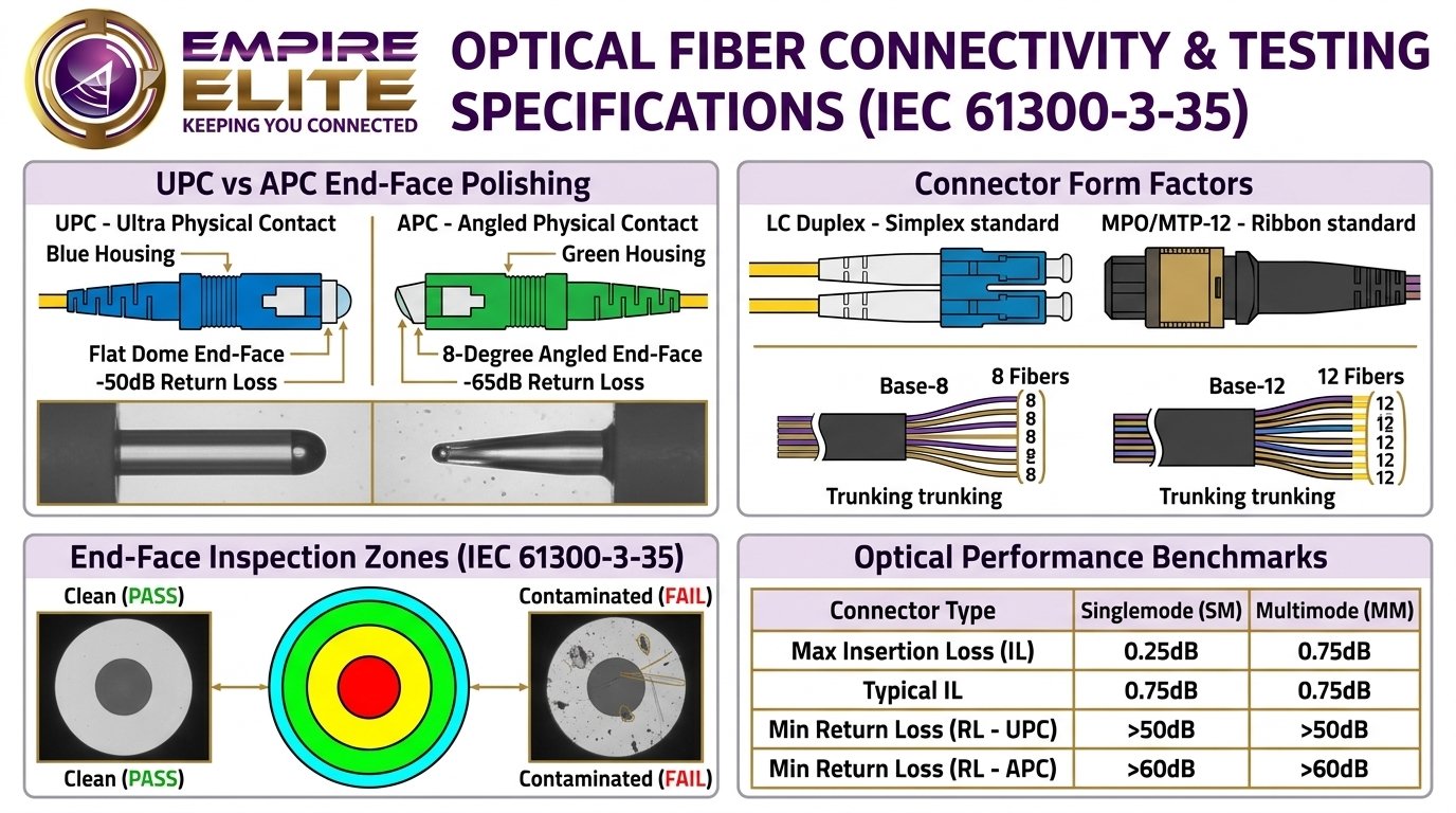
LC Duplex (Lucent Connector): The undisputed workhorse of enterprise switching. Featuring a 1.25mm ceramic ferrule, LC connectors provide reliable push-pull latching and low insertion loss. Single-mode LC connectors are available in two polish geometries:
- UPC (Ultra Physical Contact - Blue Housing): Polished flat with a slight dome curvature. Delivers \(\ge 50\text{ dB}\) return loss. Standard for corporate LANs and short-reach data centers.
- APC (Angled Physical Contact - Green Housing): Polished at an 8-degree angle. Any reflected light is deflected directly into the cladding rather than reflecting back into the laser diode. Delivers \(\ge 65\text{ dB}\) return loss. Mandatory for RF video, long-haul telco, PON (Passive Optical Networks), and high-power DWDM systems.
-
MPO/MTP Connectors (Multi-Fiber Push-On): High-density array connectors terminating 8, 12, 16, or 24 fibers in a single rectangular ferrule. MPO/MTP is the foundation of modern spine-leaf data centers, allowing rapid plug-and-play trunk cabling between core racks and patch panels:
- Base-8 Architecture: Uses 8-fiber MTP trunks, aligning directly with 40G (4x10G lanes) and 100G (4x25G lanes) transceiver architectures with 100% fiber utilization and zero dark strands.
- Base-12 Architecture: Traditional legacy trunk standard, typically split into 6 LC duplex pairs via high-density cassette modules.
7. Outside Plant (OSP) & Underground Pathway Engineering
When extending campus networks between physical buildings, fiber cables face extreme environmental stressors: water ingress, freeze-thaw soil shifts, lightning strikes, and rodent chew. Professional campus fiber design adheres to strict outside plant guidelines:
- Armored Loose-Tube Construction: Inter-building runs must utilize armored, gel-filled or dry-block water-swellable tape cables. Corrugated steel tape armor provides crush resistance up to 2,000 N and prevents rodent penetration.
- Conduit Sizing & Innerduct: Heavy-duty Schedule 40 or Schedule 80 PVC conduit (minimum 4-inch diameter) should be buried below the regional frost line (typically 36 to 48 inches deep). Install three 1.25-inch corrugated innerducts or MaxCell fabric mesh pathways to allow future cable additions without disturbing existing fibers.
- Pull Tension & Bend Radius Limits: Pulling tension must never exceed manufacturer limits (typically 600 lbs for OSP cable) using breakaway swivels and tension-monitored winches. Maintain a minimum dynamic bend radius of 20x cable diameter during pulling, and 10x cable diameter in relaxed static resting state.
- Locate Tracer Wire & Warning Tape: Non-conductive all-dielectric fiber cannot be located by underground utility locators. Empire Elite always installs a #12 AWG coated copper tracer wire alongside the conduit, accompanied by bright orange detectable underground warning tape buried 12 inches above the conduit.
8. Tier 1 (OLTS) vs. Tier 2 (OTDR) Testing & Certification
To provide verifiable warranties and insurer compliance, fiber installations must undergo rigorous two-tier certification testing:
- Tier 1 Certification (Optical Loss Test Set - OLTS): Uses an optical light source and power meter (e.g., Fluke Networks CertiFiber Pro) to measure total end-to-end insertion loss and link length across operating wavelengths (850nm/1300nm for MMF; 1310nm/1550nm for SMF). The test equipment compares measured loss against IEEE/TIA limits for a pass/fail verdict.
- Tier 2 Certification (Optical Time Domain Reflectometer - OTDR): An OTDR transmits high-power laser pulses into the fiber strand and measures backscattered and reflected light over time. This generates a detailed graphical trace identifying the exact metric location, insertion loss, and reflectance of every fusion splice, connector pair, and macrobend stress point across the entire link length.
Need Enterprise Fiber Splicing & Backbone Engineering?
Empire Elite’s certified technicians deploy precision core-alignment fusion splicing, MPO high-density trunking, and comprehensive OTDR Tier 2 certification for campuses and data centers throughout the Carolinas.
Schedule a Fiber Engineering Consultation